Over the course of two evenings after work this week, I started and completed the build of a Pete Millet Starving Student Hybrid Tube headphone amplifier. This little project was very fun and was a bit more complex than my previous DIY electronic projects.
I did take an easy-route and bought a kit from Beezar Audio. This kit came with all the components needed (except wires), a custom drilled case, and a set of relatively rare 19J6 matching tubes and priced at $150 for everything. The parts list for this project actually cost a little bit more than that, so I was pretty happy to get everything for under the cost it would have been for me to buy individual components. This is a limited edition kit that has less than 40 available at this point. Tom from Beezar has only offered this kit a couple times in the past 10 years with the last time it was offered in 2014. This is partially due to the limited availability of the tubes.
While, I won't go over every step in this process, you can easily find the overview and step-by-step guide on diyforum.com and Head-Fi. I will show some of the photos from my build.
This first photo shows the top side of the PCB with the tube sockets and a resistor for the LEDs. The socket did require some additional work. There is a pin that comes stock down the center of each socket. To use LED bulbs, the pin had to be removed by drilling the pin out of the hole. It wasn't too difficult but is a tad messy. Once it was removed, the LED can be placed in the hole and routed to the other side of the board.
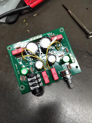
This photo above shows the mostly complete PCB layout on the bottom. There are several resistors that you can't see very well in the photo. The wiring could have been done better, but I was trying to finish this quickly. I may go back and clean up the wiring in the future. The board has the 1/4 inch female connector on the lower left and the volume pot on the lower right. One the side is the inputs for the left and right channel and up on the top of the photo are the inputs for power and the power switch.
Here is a photo of the top case installed with the board. Several fit ups were done before closing the case.
This photo shows the wiring and installation of the various input jacks to the PCB board. I only had yellow 22AWG copper available and so I had to manage with just this.
--
View the product ratings on
Antdroid's IEM Ranking List and/or Antdroid's Headphone Ranking List


great post!
ReplyDeleteis there a way to build the amp without the led tube lights?
I just ordered my kit :) hope theyre actually still in stock.
Hi David - Thanks for the comment! I believe you can just omit the LED and it'll work fine. You may want to contact Tom from Beezar audio about it. He's very responsive via email or on Head-Fi (@Tomb).
Deletethanks, looking forward to building this :)
Delete